KLAF Dissolved Air Flotation Tank
1. Operational Principle
KLAF Dissolved Air Flotation Tank is a device for the separation and purification of the suspended pollutants. It is designed to remove the suspended solids, gelatinous substance and oil in the industry and city wastewater. Wastewater to be treated enters into the inflatable segment of the self-priming aerator first through intake. The wastewater of ascent process in inflatable segment is mixed with micro bubbles generated by aerator to form a gas hydrate. When the aeration happens in the return pipe located at the bottom of floating device, a negative pressure area will be generated in the return pipe. It will cause the wastewater in the device to reflux to the aeration area, and then make the sludge treatment much better. Due to the density difference between gas hydrate and liquid, it results in a vertical upward buoyancy force. Micro bubbles adhere to the suspended solids, thereby making the suspended solids fl oat to the surface and maintain in the water surface with relying on the bubbles. It will be intermittently pushed from the floatation tank inlet to the outlet end by chain scraping residue machine and then scum will be discharged by spiral conveyor. After purification, wastewater will be discharged through overflow tank or to the next stage of treatment facilities.
2. Structure Features and Applications
This flotation device has the advantages of simple structure, convenient operation, high degree of automation, low noise, no need to install the conventional floatation device dissolved air system (dissolved gas cylinder, air compressor, and reflux pump), low operation cost and reduced power consumption (only 20% the power consumption of the conventional floatation tank). Due to high efficiency of suspended solids removal, small occupied space etc. this device is widely used in the paper, wood, tanning industry, slaughtering industry, food industries. Practice methods have proved that this floatation device has a suspended solids and oil removal rate of more than 95%.
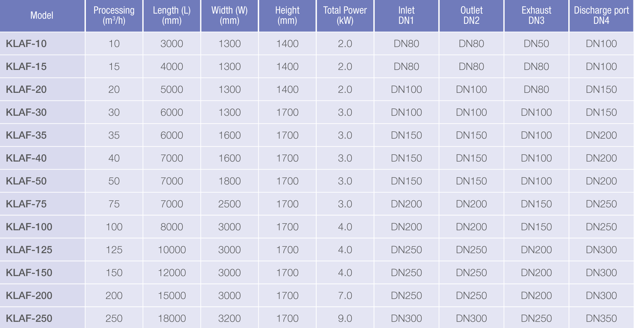
3. Main Technical Parameters

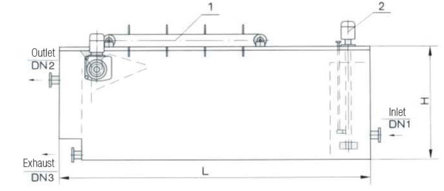
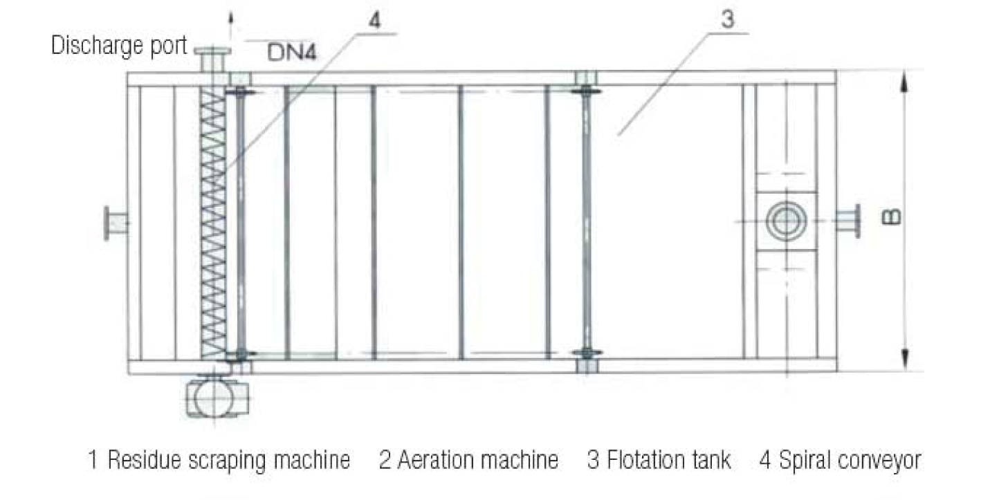
4. Equipment Outline and Schematic Diagram

